
Laser Scan to BIM Conversion: Turning Buildings into Architectural Models
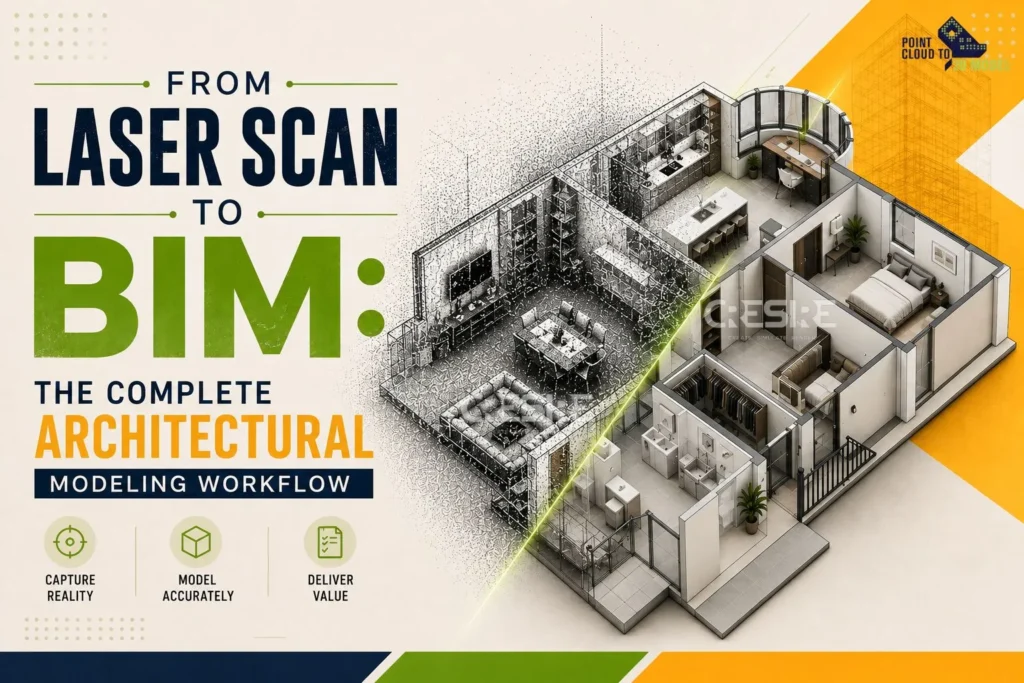
An existing building rarely looks exactly like its original drawings.
Walls may have moved. Openings may have been modified. Floors may have settled or changed over time. Services may have been rerouted, ceilings replaced, and extensions added without the original documentation ever being updated.
For an architect involved in renovations or retrofitting work, this poses a common dilemma:
How can you design with precision if the plans are not reflective of the reality of the situation?
In this context, it becomes especially important to consider laser scan to BIM conversion technology.
The use of laser scanning entails collecting millions of measurement points of the existing structure. The end result is called the “point cloud.” But a point cloud itself is not an architectural BIM model. It is the evidence from which the model is developed.
The real work begins when that measured information is interpreted into walls, floors, ceilings, doors, windows, roofs, structural elements, and other building components within a BIM environment.
The result is a digital representation of the existing building that architects and project teams can use as a foundation for design.
What Is Laser Scan to BIM Conversion?
The conversion from Laser scan to BIM is the conversion process of 3D Laser scanning data into a Building Information Modeling (BIM) model.
A scanner takes an image of the structure as a group of points in space. After registration of several scans, a group of points is created, which is known as the point cloud.
The BIM team uses the point cloud as a reference to create elements of the model. For an architectural project, these may include:
- external and internal walls;
- floors and slabs;
- ceilings;
- doors and windows;
- roofs;
- stairs;
- columns and other visible structural elements;
- façade elements;
- architectural openings;
- major building components;
- relevant MEP elements where included in the scope.
The level of information depends on the project requirements.
A model prepared for early design may focus on primary architectural geometry. A model developed for detailed renovation, coordination, or construction may require considerably more information.
This is why Scan to BIM should not be viewed simply as a file conversion.
A point cloud is measured data. A BIM model is interpreted as building information.
That difference matters.
Why Architects Use Laser Scanning for Existing Buildings
Traditional site measurement relies heavily on manual measurements, photographs, sketches, and existing drawings.
Those methods still have their place.
But large or geometrically complex buildings can make complete manual documentation difficult. Measuring every wall, opening, ceiling change, structural element, and irregular surface individually can take considerable time, and some areas may be difficult or unsafe to access.
Laser scanning changes the way existing conditions are captured.
A scanner records the physical environment from multiple positions, creating a dense spatial dataset that can later be reviewed in the office.
For an architect, this means the site can effectively become a measurable digital reference.
Instead of relying entirely on assumptions or incomplete legacy drawings, the design team can inspect the captured conditions and develop the BIM model against that information.
Existing Buildings Are Full of Small Differences
The challenge with existing buildings is rarely one dramatic error.
It is usually hundreds of small differences.
A wall may be slightly out of square. A column may not sit exactly where an old drawing shows it. A ceiling may vary in elevation. A doorway may have been relocated. A floor may not be perfectly level.
Any one of these differences may appear insignificant.
Together, they can influence design decisions.
A renovation model that reflects these conditions more accurately gives architects a stronger starting point for developing the next design.
From Laser Scan to BIM: What Actually Happens?
A successful 3D scanning laser scan to BIM workflow normally involves several stages.
The exact process varies by project, scanner, point-cloud format, BIM software, required LOD, and project standards. But the general workflow follows a logical progression:
Laser scanning → Registration → Point-cloud processing → Quality review → Point-cloud linking → BIM interpretation → Architectural modeling → QA/QC → Coordinated BIM deliverable
Each stage matters.
A mistake early in the workflow can affect everything that follows.
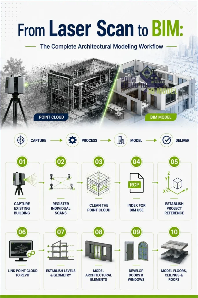
Step 1: Capture the Existing Building With Laser Scanning
The process begins on site.
Laser scanners are positioned at multiple locations throughout the building. Each scan records the surrounding environment as spatial data.
Depending on the project, scanning may capture:
- walls;
- floors;
- ceilings;
- columns;
- doors and windows;
- stairs;
- structural elements;
- visible MEP services;
- façade conditions;
- equipment;
- architectural details.
The scanner does not know that a particular collection of points represents a wall or a window.
It simply records spatial information.
That interpretation comes later.
This is one of the most important concepts for understanding laser scan to BIM conversion.
The scan captures reality.
Step 2: Register the Individual Scans
A large building usually requires multiple scan positions.
Those individual scans need to be aligned into a common coordinate framework so they form one coherent representation of the building.
This process is generally referred to as registration.
Registration is critical because a beautifully detailed scan is of limited value if different scan stations do not align correctly.
Control points, targets, survey information, scanner positioning, and the registration workflow can all contribute to the final accuracy of the point cloud.
The quality of this stage directly influences the reliability of the BIM modeling process.
Step 3: Process and Clean the Point Cloud
Raw scan data can contain more information than the BIM team needs.
There may be redundant points, temporary objects, people, equipment, vegetation, reflections, or other information that isn’t relevant to the modeling scope.
Point-cloud processing can therefore involve cleaning, cropping, organizing, classifying, or reducing unnecessary data.
Autodesk ReCap Pro supports registration, cleaning, cropping, organization, classification, and preparation of point clouds for use in workflows such as Revit. Autodesk’s current documentation also notes that ReCap can convert different captured-data formats into point-cloud formats that can be used by Revit and other Autodesk applications.
The objective isn’t to remove information simply for the sake of making the file smaller.
It is to create a point cloud that is practical to work with while retaining the information required for the project.
Step 4: Index the Point Cloud for BIM Use
Before the point cloud can be used effectively in Revit, it generally needs to be prepared in a supported indexed format.
For Autodesk workflows, ReCap Pro can index point-cloud data into RCP/RCS formats, which can then be linked into Revit. Autodesk’s current support guidance specifically states that programs such as Revit link indexed RCP/RCS point clouds.
This technical step is easy to overlook because it happens before architectural modeling.
But it matters.
A poorly prepared point cloud can create problems with performance, positioning, file management, or accessibility later in the project.
Step 5: Establish Coordinates and Project Reference
Once the point cloud is ready, it needs to be positioned correctly relative to the BIM project.
This may involve:
- project base point;
- survey point;
- shared coordinates;
- building orientation;
- levels;
- known survey references;
- project north and true north;
- elevation references.
For larger projects, survey information may be particularly important.
A model can be geometrically accurate and still be incorrectly positioned if its coordinate relationship with the survey or wider project environment hasn’t been established properly.
That is why coordinate management should be addressed before detailed modeling begins.
Step 6: Link the Point Cloud Into Revit
The point cloud becomes the primary visual reference for developing the architectural BIM model.
Rather than drawing walls based on assumptions, the BIM modeler can inspect the point cloud and place model elements against the measured building conditions.
The point cloud can be reviewed in plans, sections, elevations, and 3D views.
This is where the workflow starts to feel very different from traditional CAD drafting.
The modeler is no longer simply tracing a drawing.
They are interpreting a measured three-dimensional environment.
Step 7: Establish Levels and Building Geometry
Before modeling every element, the major building framework needs to be established.
This may include:
- floor levels;
- roof levels;
- major grids;
- primary wall positions;
- floor boundaries;
- building orientation;
- major vertical transitions.
Levels are particularly important because they influence how the rest of the architectural model is organized.
If an existing floor is uneven or the building contains multiple elevations, the BIM team needs to determine how those conditions should be represented based on the project requirements.
This is where professional judgement becomes important.
The point cloud provides measurements.
It does not decide how the BIM model should be structured.
Step 8: Model Architectural Elements From the Point Cloud
Now the actual architectural BIM development begins.
Walls can be modeled against the visible wall surfaces. Floors can be developed from measured floor geometry. Doors and windows can be placed based on their actual locations and dimensions.
The same principle applies to other architectural components within the agreed scope.
The process is not necessarily a point-for-point tracing exercise.
The modeler must decide which physical conditions should become BIM elements and how those elements should be represented.
For example, an existing wall may contain layers of finishes, irregularities, or construction tolerances that are visible in the scan.
Whether those conditions become separate modeled elements depends on the required LOD and the purpose of the model.
This is why laser point cloud to BIM conversion requires both technical modeling skills and an understanding of architectural construction.
Step 9: Develop Doors and Windows
Doors and windows can be particularly useful in an existing-building BIM model because they influence both documentation and design development.
Their locations, widths, heights, sill conditions, frames, and surrounding wall geometry can be assessed against the point cloud.
However, not every visible detail needs to become a fully customized BIM family.
If the project only requires basic architectural representation, a standard family with appropriate dimensions may be sufficient.
If the project involves historic restoration or detailed façade documentation, considerably more information may be necessary.
Again, the required model use should determine the level of detail.
Step 10: Model Floors, Ceilings and Roofs
Existing floors and ceilings can present more complexity than they appear to from a photograph.
A floor may have variations in elevation. A ceiling may step between areas. A roof may contain multiple planes or irregular geometry.
The point cloud allows the BIM team to investigate these conditions in three dimensions.
Sections are especially useful.
An architectural plan may tell you where a wall is located. A section can show how that wall relates to floor levels, ceiling heights, structural elements, and roof geometry.
This is one of the strongest advantages of developing the model from a point cloud.
The information is inherently spatial.
When Should Irregular Geometry Be Modeled Exactly?
This is one of the practical questions architects and BIM managers often need to answer.
Existing buildings are rarely perfect.
If every minor surface variation is modeled exactly, the BIM model can become unnecessarily complex. If all irregularities are ignored, the model may no longer represent the building accurately enough for its intended use.
The answer depends on the project.
For example:
Concept design:
Major geometry and spatial relationships may be sufficient.
Renovation design:
Existing wall positions, openings, levels, shafts, and significant irregularities may need greater accuracy.
Detailed construction:
Elements affecting installation and fabrication may require substantially more definition.
Historic or heritage work:
Architectural irregularities and decorative elements may warrant much greater attention.
The goal isn’t to reproduce every point.
It is to reproduce the information that matters.
Laser Scan to BIM Software: What Tools Are Used?
The software used depends on the point-cloud source, project requirements, BIM platform, and modeling scope.
A common Autodesk-based workflow can involve:
Autodesk ReCap Pro
ReCap is commonly used for point-cloud preparation, registration, indexing, cleaning, organization, and other reality-capture workflows. Autodesk currently positions ReCap Pro as a tool for working with laser scans and creating digital representations of real-world assets.
Autodesk Revit
Revit is used to develop the actual BIM model from the point-cloud reference.
Architectural elements can be created and organized into a structured BIM environment rather than remaining as raw scan data.
Navisworks
Navisworks can be used where multidisciplinary coordination and model review are part of the project workflow.
AutoCAD
CAD may still be useful for extracting or producing 2D documentation, profiles, details, or supplementary drawings depending on project requirements.
Other Point-Cloud Platforms
Projects may also involve specialist point-cloud processing, registration, visualization, or scan-to-mesh platforms depending on the data source and workflow.
The important thing is not choosing software because it is popular.
The software should support the required workflow from captured reality → processed data → BIM model → project deliverable.
What Has Changed in Scan-to-BIM Workflows in 2026?
The underlying process of interpreting point clouds into BIM remains important, but the technology around it is evolving.
For example, ReCap Pro 2026 introduced enhanced scan-to-mesh capabilities and a Revit integration that can bring segmented mesh geometry into Revit as families through a dedicated workflow. Autodesk describes this as a way of reducing some manual modeling effort for complex elements.
This is worth watching, but it doesn’t mean automated conversion has replaced BIM modeling.
A mesh is not automatically a correctly structured architectural BIM model.
Someone still needs to decide:
- what category an element belongs to;
- what level of detail is appropriate;
- how it should be represented;
- which dimensions matter;
- how it relates to other building elements;
- what information should be attached to it;
- whether the result is suitable for the project’s intended use.
Automation can reduce repetitive work.
It does not remove the need for architectural interpretation.
Scan to BIM for Renovation and Retrofit Project
Renovation is one of the clearest applications of laser scan to BIM conversion.
An architect working on an existing building needs to understand the starting condition before designing the proposed condition.
A reliable existing BIM model can provide a foundation for:
- space planning;
- refurbishment;
- adaptive reuse;
- retrofit;
- extension design;
- façade renovation;
- heritage documentation;
- MEP upgrades;
- structural modifications;
- construction planning.
The value becomes particularly apparent when existing documentation is incomplete.
Instead of spending weeks trying to reconcile old drawings with site measurements, the project team can work from a measured digital reference.
That doesn’t make the existing building predictable.
It makes its unpredictability easier to see.
Scan to BIM Is Not Just About Architectur
Although this article focuses on architectural models, the same existing-condition information can support wider BIM workflows.
A project may require architectural, structural and MEP information to be developed from the same point cloud.
For example, an existing renovation project may need:
Architectural BIM
Walls, floors, ceilings, doors, windows and other architectural elements.
Structural BIM
Columns, beams, slabs, foundations and visible structural components.
MEP BIM
Existing ducts, pipes, equipment, cable trays and other services where visible and included in the scope.
Developing these disciplines from a common reality-capture source can give the project team a more consistent understanding of existing conditions.
It can also provide a stronger foundation for multidisciplinary coordination.
What Can Go Wrong With Laser Scan to BIM?
Laser scanning itself is highly capable, but the overall workflow can still produce poor results if the process isn’t managed carefully.
Incomplete Scan Coverage
If important areas were not captured, the modeler may have to rely on other information or assumptions.
Poor Registration
Misaligned scans can introduce errors into the point cloud that later appear as apparent building movement or geometry inconsistencies.
Incorrect Coordinates
A model can be accurately developed but incorrectly positioned relative to the project survey.
Over-Modeling
Trying to reproduce every minor irregularity can make the BIM model unnecessarily heavy and difficult to use.
Under-Modeling
Simplifying important geometry too aggressively can make the model unsuitable for the intended design or coordination purpose.
Wrong Interpretation
A point cloud doesn’t label objects.
A modeler has to interpret what the points represent.
That interpretation requires architectural and BIM knowledge.
Quality Control: The Step That Should Never Be Skipped
A model can look convincing and still contain errors.
That is why QA/QC should be part of the laser scan to BIM conversion workflow rather than an afterthought.
A useful review can compare the BIM model against the point cloud in:
- plan;
- elevation;
- section;
- 3D;
- critical building areas;
- openings;
- floor levels;
- major wall locations;
- roof geometry;
- complex architectural conditions.
Critical areas should receive additional attention.
A project may have dozens of ordinary rooms but one complicated stair, façade, roof intersection, or irregular structural zone that becomes particularly important to the design.
Quality control should therefore consider project risk, not simply check every element with the same level of attention.
What LOD Should a Scan to BIM Model Have?
There is no single LOD that applies to every scan-to-BIM project.
The required level depends on what the model is being used for.
A client developing an early renovation concept may need a different model from a contractor preparing detailed construction information.
For example:
LOD 200:
Generalized existing geometry suitable for early design understanding.
LOD 300:
More accurate architectural elements with defined size, location, and relationships suitable for design development and coordination.
LOD 350:
Additional representation of interfaces and relationships that may be important for construction coordination.
LOD 400:
Detailed modeling appropriate for fabrication or installation-related workflows where required.
These definitions should always be aligned with the project’s BIM requirements and contractual scope.
A higher LOD should not be requested simply because it sounds better.
The model should contain the level of information that the project actually needs.
Why Architectural Interpretation Still Matters
This is perhaps the most important point in the entire workflow.
A scanner captures millions of points. It doesn’t create an architectural model by itself. Someone needs to interpret the point cloud and decide:
Is this a wall?
Where does the wall actually terminate?
Is this surface structural or a finish?
Is this ceiling level intentional or a temporary condition?
Should this irregularity be modeled?
Is this object part of the building or temporary site equipment?
What Revit family best represents this element?
Those decisions require more than software knowledge. They require an understanding of architecture, building construction, BIM standards, and the intended use of the model.
That is why a successful 3D scanning laser scan to BIM workflow combines reality-capture technology with professional modeling judgement.
Why Architectural Interpretation Still Matters
This is perhaps the most important point in the entire workflow.
A scanner captures millions of points. It doesn’t create an architectural model by itself. Someone needs to interpret the point cloud and decide:
Is this a wall?
Where does the wall actually terminate?
Is this surface structural or a finish?
Is this ceiling level intentional or a temporary condition?
Should this irregularity be modeled?
Is this object part of the building or temporary site equipment?
What Revit family best represents this element?
Those decisions require more than software knowledge. They require an understanding of architecture, building construction, BIM standards, and the intended use of the model.
That is why a successful 3D scanning laser scan to BIM workflow combines reality-capture technology with professional modeling judgement.
FAQs
Common workflows may use Autodesk ReCap Pro for point-cloud preparation and Autodesk Revit for BIM modeling. Other software can be introduced for point-cloud processing, coordination, visualization, or specialized requirements depending on the project. Autodesk currently documents ReCap Pro workflows for preparing point clouds for Revit.
A laser scan produces point-cloud data rather than a finished Revit BIM model. The point cloud can be prepared and linked into Revit, where BIM elements are developed from the measured information. Newer ReCap workflows can also create segmented meshes and support bringing certain mesh geometry into Revit as families, but professional interpretation and model development are still required for a complete BIM deliverable.
A point cloud is a collection of measured spatial points captured from the physical environment. A BIM model is a structured digital representation containing modeled building elements and associated information. The point cloud provides the measured reference; the BIM model interprets that reference into usable building information.
Yes. It is particularly useful when existing drawings are incomplete, outdated, or unreliable. A point-cloud-based BIM model can provide architects with a more reliable representation of existing walls, floors, openings, ceilings, roofs, and other building conditions before renovation or retrofit design begins.
Accuracy depends on the scanner, survey control, registration, point-cloud quality, modeling methodology, LOD, and QA/QC process. The BIM model is an interpretation of the point cloud, so its required accuracy should be established according to the intended project use rather than assumed from the scanner specification alone.
The required LOD depends on the purpose of the model. Early design may require generalized existing conditions, while detailed renovation, coordination, construction, or fabrication workflows may require more developed geometry and information. The LOD should be agreed as part of the project’s BIM requirements.
Yes. Depending on the project scope, point-cloud data can be used to develop architectural, structural, and MEP existing-condition models. This can be particularly useful for renovation and retrofit projects where multiple disciplines need to understand the same existing building conditions.
Not necessarily. Laser scanning can capture highly detailed spatial information, but the appropriate survey scope depends on the project. Survey control, georeferencing, site verification, photographs, material investigation, and other field information may still be required depending on the design and contractual requirements.