
What Happens Between a Point Cloud and CAD Model? A Practical AEC Guide
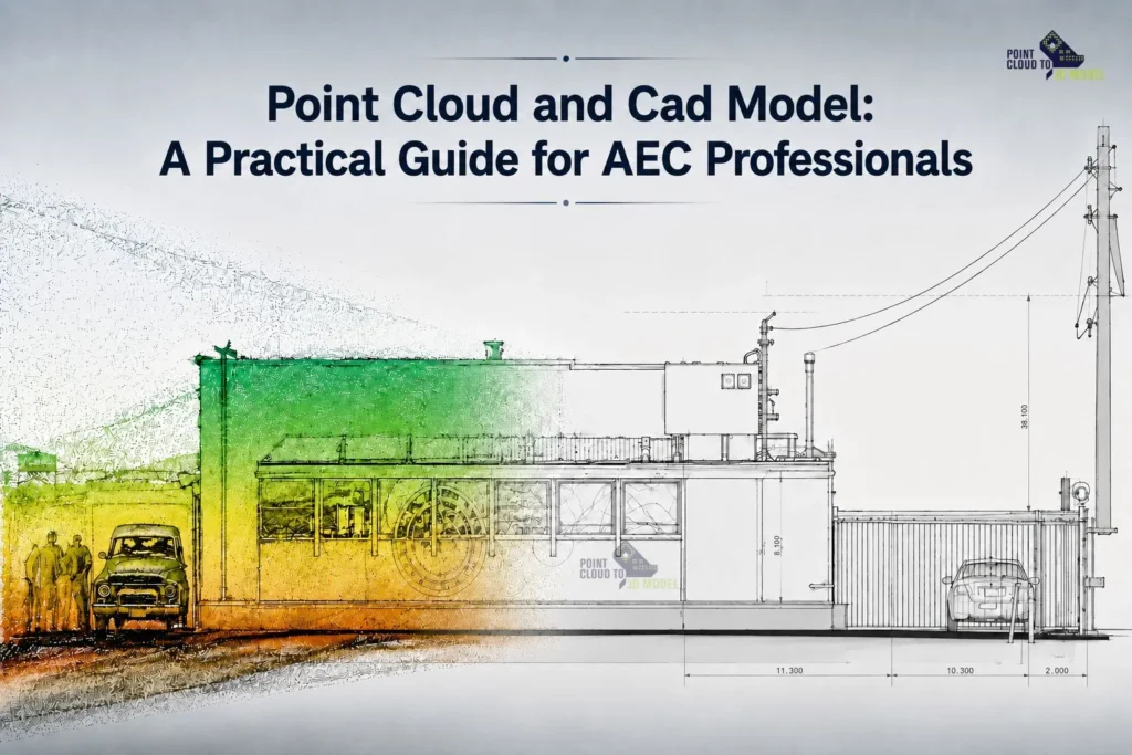
A laser scanner can capture millions of points from a building, but those points do not automatically become floor plans, elevations, or construction drawings. There is an important workflow between capturing existing conditions and creating a usable Point Cloud to CAD Model.
For architects, engineers, surveyors, contractors, and BIM professionals, understanding this process helps explain where accuracy comes from and why scan data still requires careful interpretation.
A Point Cloud Is Not a CAD Drawing
A point cloud is essentially a three-dimensional collection of measured points representing surfaces captured during a survey.
Depending on the scanning method and project, those points can represent:
- Walls and partitions
- Floors and ceilings
- Doors and windows
- Roofs
- Columns and beams
- Equipment
- Pipes and ducts
- Building façades
- Other visible site elements
The important word here is captured.
The scanner records what it can see. It doesn’t understand the building in the way an architect or CAD technician does.
A wall may appear as thousands of points, but the finished drawing needs to represent that wall using appropriate CAD geometry. A doorway needs to become an opening with defined edges. A floor needs an elevation. A curved façade needs to be interpreted rather than simply traced point by point.
This is why point cloud and CAD model are better understood as an interpretation and documentation workflow, not a file-format conversion.
What Happens Before CAD Modeling?
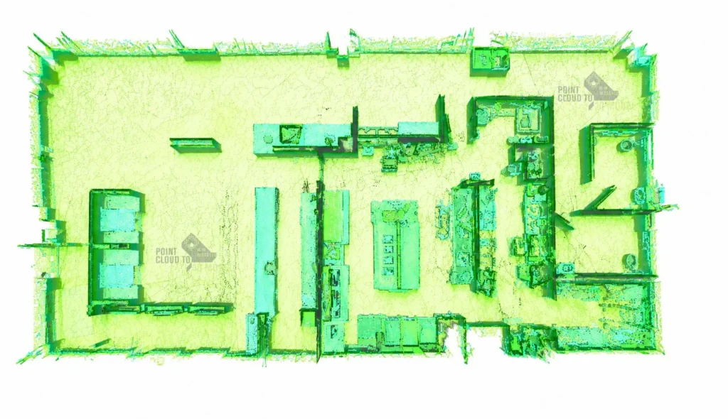
The quality of the final drawing depends heavily on what happens before the first line is drawn.
Scan Registration and Alignment
Large buildings are rarely captured from a single scanner position. Multiple scans are combined and registered into a common coordinate system.
If registration is inconsistent, the problem can carry through into the drawings.
Before modeling begins, the team needs to understand how the scans are aligned and whether the available coordinate information is suitable for the intended deliverables.
Cleaning and Preparing the Data
Raw scan data can contain points that aren’t useful for architectural documentation.
People moving through the building, vehicles, temporary objects, reflective surfaces and scanning noise can all appear in the dataset.
The objective isn’t necessarily to remove everything except the building.
It is to make the important geometry easier to interpret.
Checking Coverage
A point cloud can look comprehensive while still containing gaps.
Furniture may hide walls. Equipment can obstruct services. Ceiling areas may not be fully visible. Exterior façades may have sections that were inaccessible during scanning.
These gaps matter because CAD modeling cannot recover information that the scan never captured.
If an area is uncertain, it should be identified and reviewed rather than quietly filled in with assumptions.
How Does a Point Cloud Become a CAD Model?
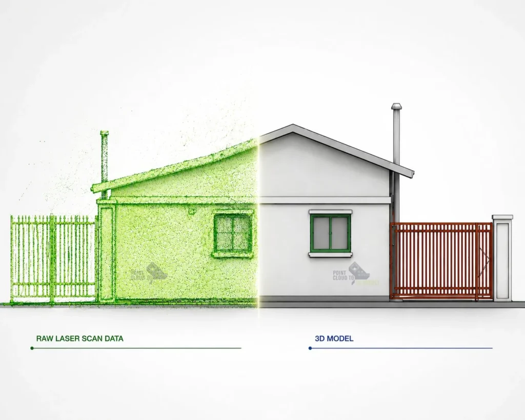
Once the scan data is prepared, the actual interpretation begins.
1. Identify the Building Elements
The modeler studies the point cloud from different viewpoints, sections and elevations to understand the geometry.
For an architectural floor plan, this could involve identifying:
- Wall faces
- Openings
- Door locations
- Window positions
- Columns
- Stairs
- Major fixed elements
The same point cloud may be examined differently depending on whether the required output is a plan, section, elevation or 3D CAD model.
2. Establish Levels and References
Accurate references provide consistency across the drawing set.
Depending on the project, this can include:
- Levels
- Grids
- Axes
- Reference planes
- Building orientation
- Coordinate systems
This becomes particularly important when existing-condition drawings need to be coordinated with survey information or future design drawings.
3. Develop CAD Geometry
The identified building elements are then represented using appropriate CAD geometry.
Depending on the drawing requirement, this may include:
- Lines
- Polylines
- Arcs
- Hatches
- Blocks
- Dimensions
- 3D solids
For a point cloud to 2D CAD project, the output might include floor plans, reflected ceiling plans, elevations and sections.
For projects requiring more detailed 3D documentation, the geometry may be developed further into three-dimensional CAD elements.
The objective isn’t to trace every individual point. The objective is to create the level of geometric information the project actually needs.
What Makes Point Cloud CAD Modeling Challenging?
Even detailed scan data can present difficult modeling conditions.
Occlusion is one common issue. Equipment or furniture may hide portions of walls, columns, or MEP systems. Historic buildings can present another challenge because floors and walls may be irregular rather than perfectly straight.
MEP areas can also be difficult to interpret because pipes, ducts, cable trays, and equipment often overlap. Multiple views and sections may be required to understand their position.
Large datasets can add another layer of complexity. The objective is not to model every visible object but to create the information required by the project.
A reliable point cloud CAD conversion workflow should avoid treating uncertain information as confirmed geometry. If the scan does not provide enough evidence, the area should be reviewed or clearly identified rather than guessed.
Accuracy and QA/QC
Quality control is important prior to providing CAD drawings. There needs to be a comparison between the completed geometry and the initial point cloud in order to find any differences.
Checks normally performed include:
- Measurements and dimensions
- Location and thickness of walls
- Floor and ceiling elevations
- Structural elements
- MEP locations
- Alignment with the point cloud
- Layers and drafting requirements
- Project tolerances required
The required tolerance will depend upon the purpose of the drawings. Renovation documentation may have different requirements from fabrication or detailed construction work.
A Point Cloud and CAD Model should therefore be planned around the final deliverables. The required accuracy and level of detail should be established before modeling starts.
Where Is Point Cloud to CAD Used?
The workflow is particularly useful when existing documentation is incomplete, outdated or unavailable.
Renovation and Retrofit
Existing floor plans and elevations can provide a reliable starting point for developing proposed alterations.
As-Built Documentation
Laser scanning can capture existing conditions and provide the basis for updated architectural drawings.
Historic Buildings
Irregular geometry and complex existing conditions can be documented more effectively than through conventional manual measurement alone.
Structural Projects
Structural elements can be documented to support assessment, modification and coordination.
MEP Projects
Existing service routes and equipment can be represented in CAD where the scan provides sufficient visibility.
Construction Verification
Captured site conditions can be compared with drawings to identify differences between documented and actual conditions.
Point Cloud to CAD vs. Point Cloud to BIM
Both processes can be done from the same point cloud data set, but their end results would differ.
Point Cloud and CAD Model is all about geometric documentation, it is useful for plans, sections, elevations, details and some 3D applications.
Point Cloud to BIM process will produce structural building elements with information like type, material, dimensions and other data.
It is a matter of project requirement whether one should go for a CAD process or BIM process.
Key Takeaways for AEC Teams
It should be noted that there is no automatic translation from the scan into CAD drawings. It is necessary to go through stages such as registration, cleaning, interpretation, creation of reference documents, modeling, drafting and checking.
The quality of the transfer from point clouds to AutoCAD, from point clouds to 2D CAD, or any other CAD document will depend both on the quality of the capture of the initial data and on the interpretation of this data.
A proper point cloud and CAD model begin with clear project specifications. The scanning gives the measurements of the current state of things, and the CAD model represents this state in an organized form.
Thus, it can be argued that point cloud CAD conversion is the transition from captured reality to design documentation.
FAQs
The point cloud is a large set of millions of points obtained by laser scanning and other forms of reality capture. The CAD model, however, takes all the scanned points and organizes it into geometry like lines, polylines, arcs, dimensions, blocks, and 3D geometry. The point cloud is the actual physical state, while the CAD model is the structured documentation useful for design, renovation, coordination, or construction.
Point cloud to CAD conversion usually starts from scan registration, data clean up, coverage check, building element interpretation, levels and reference points definition, creation of CAD models, and QA/QC check. It does not simply trace all the scanned points. The modeler studies the scan and then models the geometry.
The point cloud data may be used within AutoCAD compatible environment, however, it is not an automatically generated CAD drawing file. It may require interpretation and modeling of the walls, doors, windows, structures, and MEP systems in order to turn it into the CAD geometry.
Based on the type of work, a point cloud may be used for preparing various drawings such as floor plan drawings, elevations, sections, reflected ceiling plans, façade drawings, structure drawings, MEP drawings, and 3D CAD models.
The accuracy is determined by several factors, including scanner accuracy, scan registration, site coverage, data quality, tolerances within the project, and the process of modeling. There must be a specified accuracy requirement before the point cloud to CAD process takes place.
Scan to CAD is widely used for renovation, retrofit, as-built documentation, historical surveys, structural analysis, MEP documentation, and construction verification. Scan to CAD is especially useful when there are no accurate drawings available.
Yes. The same laser scan data can be used for point cloud to 2D and 3D CAD modeling. It all depends on the needs of the project and the level of detail needed in the drawings.
In case where the element is hidden by furniture, machines, walls, and other obstacles, there will not be enough data available in the point cloud to model the object. This should be investigated further through the site information.